How to create a PCB footprint from a datasheet
How to Create a PCB Footprint From a Datasheet
To create a PCB footprint from a datasheet, identify the exact package variant, capture the package drawing or recommended land pattern, describe the required output precisely, generate the footprint, and validate every critical dimension before using it in a design. Neurocad accelerates that process by reading the source documentation and generating an editable preview that can be sent to your existing CAD tools.
Whole-document scanning is available and can work well, but targeted capture reduces ambiguity and gives you more control over the source used for generation.
Short answer:
Upload the datasheet, capture the exact package information, tag it as a footprint, write a specific prompt, generate the artifact, inspect and edit the SVG preview, validate it against the source and your library rules, then send it to Altium, KiCad, OrCAD, Mentor, Fusion, or SolidWorks.
What is a PCB footprint?
A PCB footprint is the physical land pattern used to place and connect a component on a printed circuit board. It normally includes copper pads, pad numbering, component and courtyard outlines, pin 1 identification, and other assembly or manufacturing information required by the target ECAD library.
The schematic symbol describes the component logically; the footprint describes how the packaged component occupies and connects to the board physically. A correct pin count is not enough. Pitch, pad geometry, package orientation, body dimensions, numbering direction, and clearances must all agree with the selected package and the organization’s library standards.
Before you start
Have the following ready:
- A Neurocad account. New users can begin with a free trial. Click here to get started.
- The source file for the component. Neurocad accepts datasheet images, PDFs, JPGs, PNG, SVG, and BSDL sources.
- The exact manufacturer part number and package code.
- The package drawing, recommended land pattern, or dimensional table for that package.
- Your target CAD tool and any organization-specific library rules.
- Neurocad Link installed and connected if you plan to send the generated artifact directly to a desktop CAD application.
Important: A single datasheet can describe several package variants. Confirm the package code before generating anything. Pin count alone may not uniquely identify the correct body size, pitch, or lead style.
Step 1: Open Neurocad's artifact generator
Once you're signed in, you will automatically start in Neurocad's Create page. Select Library Parts. This opens the dedicated workflow for one-off library-part generation; no recipe is required.
Step 2: Upload the component source
In Part 01, select + Open file and upload the relevant datasheet, design file, or image. Supported source types include datasheet images, PDFs, JPGs, PNG, SVG, and BSDL sources.
After the file is added, choose between two source-selection approaches:
- Scan the whole file. Move directly to the prompt and let Neurocad interpret the complete document.
- Capture the relevant region. Select only the pinout image, pinout table, package drawing, recommended land pattern, or footprint image required for the artifact.
Step 3: Decide whether to scan or capture
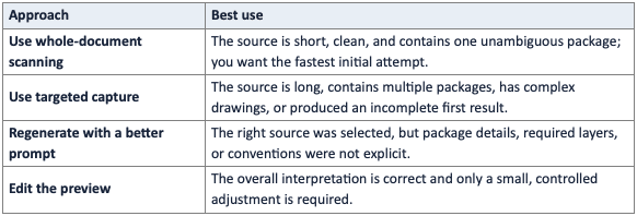
Whole-document scanning is convenient when the source is short, clearly structured, and limited to one package. Targeted capture is the more reliable choice when:
- The datasheet contains several footprint or package variants.
- The source is more than 100 pages long.
- The source is a scan. (Such as a datasheet file created several years ago.)
- The first whole-document result does not render the pinout or footprint correctly.
- The scan omits one or more pinouts or footprints.
- You want to control exactly which drawing or table is treated as authoritative.
If speed and accuracy are both priorities, start with a targeted capture for any long or multi-package datasheet.
Step 4: Capture and tag the package information
To capture a specific source region:
- Click on the uploaded file icon to reveal the camera icon.
- Select the camera icon to open the Capture window to preview the file's pages.
- Navigate to the page(s) containing the package drawing, recommended land pattern, or dimension table.
- Resize the capture frame so it includes the complete drawing, its dimension labels, units, notes, and pin 1 indicator.
- Tag the selection as either Symbol or Footprint.
- Select Capture.
- Repeat the process if another table or drawing is to be generated with this batch.
Capture tip: Try to only include the necessary information. Do not crop so tightly that the units, drawing number, package code, tolerances, notes, or dimension legend disappear. Those details often determine whether the generated geometry is correct.
Step 5: Write a precise prompt
Describe exactly what Neurocad should produce. You can start with a preloaded prompt, adapt an example, or write your own. Accuracy improves when the prompt resolves details that the image alone may not make explicit.
Include as many of the following as apply:
- Manufacturer and complete part number
- Package code and package family
- Pin count and pitch
- Nominal body dimensions
- Pin 1 orientation or numbering direction
- Required layers and markings, such as courtyard, assembly outline, silkscreen, and pin 1 indicator
- The target CAD tool or library convention
- Any organization-specific naming, pad-shape, density-level, or clearance requirements
If the first result is incomplete or inaccurate, rewrite the prompt with more specific terminology and regenerate. A more precise prompt is often faster than manually correcting an artifact produced from an ambiguous request.
Prompt pattern: Create one PCB footprint for [manufacturer part number], package [package code and family], with [pin count] pins at [pitch]. Use the captured drawing as the dimensional source. Preserve pin 1 orientation. Include [required layers and markings]. Apply [library or manufacturing rules]. Surface any inferred dimensions for review before release.
Step 7: Generate the footprint
Select Send Arrow. Neurocad processes the selected source and prompt, then displays the result as an SVG preview. Generation reduces the time spent reading dimensions, building pads, numbering pins, and drawing supporting layers by hand.
Step 8: Inspect and edit the preview
Review the generated SVG files before sending it to a CAD tool. Confirm that the previews match the chosen package. Footprints will automatically generate IPC density levels (L, N, M), and 3D models (if applicable).
At minimum, inspect:
- Pad count, numbering sequence, and pin 1 location
- Pitch and spacing between pad centers
- Pad dimensions and shapes
- Body, assembly, silkscreen, and courtyard geometry
- Units, orientation, origin, and rotation conventions
- Any inferred dimensions or tolerances
- The mapping between the schematic symbol and physical pad numbers
Edit the artifact when needed. If the overall interpretation is wrong, return to the source selection or prompt, provide a tighter capture or more specific instructions, and regenerate.
Step 9: Validate before design use
Generated footprints should pass the same release checks as manually created library parts. Compare the artifact with the manufacturer’s package drawing and recommended land pattern, then apply the organization’s normal DRC, assembly, and manufacturing review.
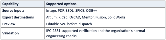
Neurocad supports IPC-2581 in verification and validation workflows. When IPC-2581 data is available, use it alongside the datasheet and your CAD-library checks to strengthen traceability between the generated artifact and downstream manufacturing data.
Do not assume that a mechanical package outline alone specifies the manufacturer’s preferred copper land pattern. If the datasheet does not provide recommended pad geometry, review any derived pads against your approved standards and manufacturing process before releasing the part.
Step 10: Send the footprint to your CAD tool
After inspection and validation, send the finished artifact to the connected CAD environment. Neurocad exports to Altium, KiCad, OrCAD, Mentor, Fusion, and SolidWorks. For CAD delivery, keep Neurocad Link running and confirm that the destination application is open and connected.
Worked example: selecting the right package from a multi-package datasheet
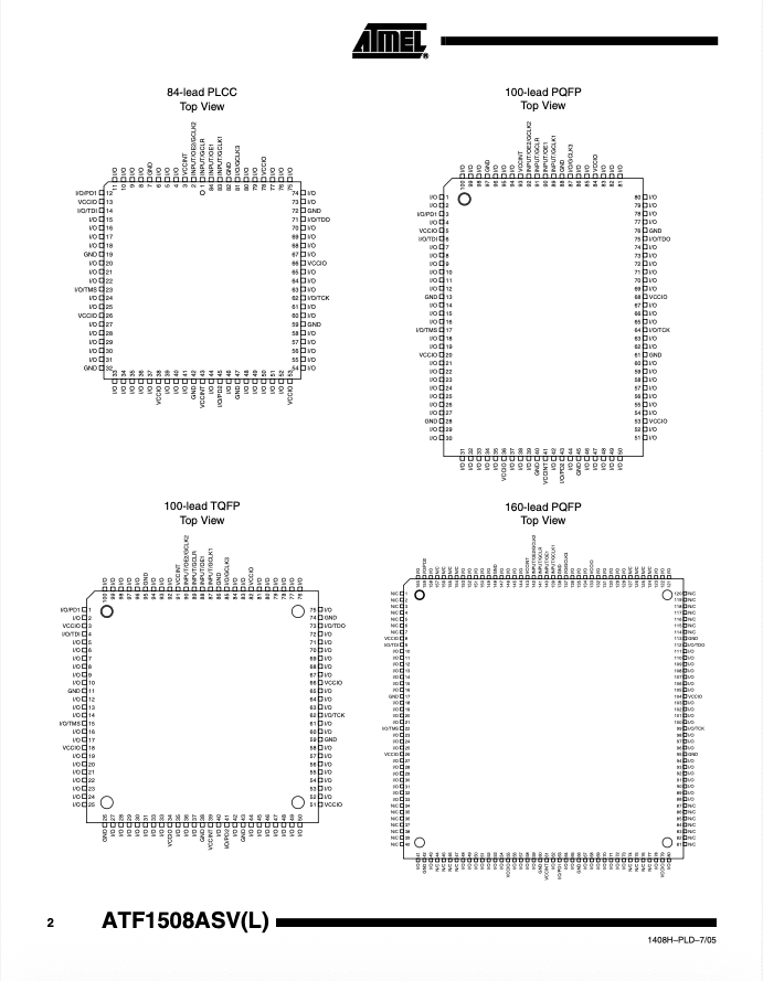
A ATF1508ASV/ASVL datasheet is a useful example because one 28-page PDF covers four physical packages: 84-lead PLCC, 100-lead PQFP, 100-lead TQFP, and 160-lead PQFP. Asking a system to “create the 100-pin footprint” is still ambiguous because the document contains both a 100-lead PQFP and a 100-lead TQFP.
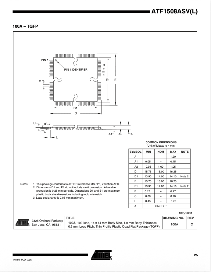
For the 100-lead TQFP variant, the ordering information identifies package code 100A. The package drawing on page 25 specifies a 14 x 14 mm nominal body and 0.50 mm lead pitch, with a visible pin 1 identifier and dimensional notes.
Recommended source selection:
- Open the datasheet in the Capture window.
- Navigate to page 25, labeled 100A - TQFP.
- Capture the full package drawing, common-dimensions table, package title, notes, and pin 1 indicator.
- Tag the capture as Footprint.
- Use a prompt that explicitly identifies package 100A and the 100-lead TQFP variant.
Example prompt: Generate one PCB footprint for the ATF1508ASV/ASVL in package 100A: a 100-lead TQFP with a 14 x 14 mm nominal body and 0.50 mm pitch. Use the captured package drawing and dimensional table as the source. Preserve the indicated pin 1 corner and correct counterclockwise pad numbering. Include the courtyard, assembly outline, silkscreen, and pin 1 marking.
Why this works: the capture removes the other three package variants from consideration, while the prompt repeats the package code, family, body size, pitch, and orientation. Neurocad receives a narrower source and a clearer statement of intent, improving both speed and accuracy.
Whole-document scan or targeted capture?
Accuracy checklist
Before approving a generated footprint, verify:
- The manufacturer part number and package code match the selected source.
- The pad count, numbering sequence, and pin 1 orientation are correct.
- Pitch, package dimensions, and pad geometry use the correct units.
- Silkscreen does not cross exposed copper or violate the chosen library rules.
- Courtyard and assembly outlines meet the organization’s standards.
- The schematic-symbol pin mapping agrees with the physical footprint.
- Any inferred or derived dimensions have been reviewed.
- The footprint passes the target tool’s DRC and the normal library release process.
- IPC-2581 validation data has been checked where it is part of the workflow.
Supported sources and destinations
Frequently asked questions
Can Neurocad create a PCB footprint directly from a PDF datasheet?
Yes. Upload the datasheet, PDF, JPG, PNG, SVG, or BSDL and either scan the complete document or capture the relevant package drawing, tag the source as a footprint, and describe the required artifact in the prompt. Targeted capture is recommended for long documents and datasheets with multiple packages.
Do I need to build a recipe first?
No. From Create, select Library Parts to open the workflow. Recipes are useful when you want to automate or reuse a multi-step process, but they are not required for generating one-off footprints.
What information should I capture from the datasheet?
Capture the complete recommended land pattern when one is provided. Otherwise capture the package drawing and any related dimension table, notes, tolerances, units, package code, and pin 1 indicator. Include enough context for the drawing to be interpreted correctly.
How can I improve footprint-generation accuracy?
Select the exact package source, use a specific prompt, and repeat critical details such as package code, pin count, pitch, body size, and pin 1 orientation. If a whole-document scan is incomplete, capture the relevant drawing and regenerate. Always inspect and validate the final artifact.
What if the datasheet contains several packages?
Confirm the ordering code for the exact component variant, then capture only that package’s drawing and dimension information. State the package code and family in the prompt. Do not rely on pin count alone when more than one package shares it.
Which file types can Neurocad read?
Neurocad supports PDF, JPG, PNG, SVG, BSDL, SPICE, and ODB++, and 3D CAD files. These sources include datasheets, package drawings, schematics, BOMs, and 3D models.
Which CAD tools can receive Neurocad output?
Neurocad exports to Altium, KiCad, OrCAD, Mentor, Fusion, and SolidWorks. Neurocad Link connects browser-generated artifacts with supported desktop CAD applications.
Should I still validate an AI-generated footprint?
Yes. Treat the generated artifact as an accelerated engineering output, not an exemption from library control. Compare it with the manufacturer source, review inferred dimensions, run the target tool’s checks, and complete the organization’s normal approval process.
Turn a datasheet into a design-ready footprint
Manual footprint construction requires repeated interpretation, measurement, data entry, and checking. Neurocad compresses those steps by extracting the relevant intent from the source and generating an editable artifact for the tools your team already uses.
For the fastest reliable result, capture the exact package drawing and tell Neurocad precisely what to build. Review the output, validate it, and move it into your normal CAD workflow. We've clocked it under 3 minutes.
Start your free trial at neurocad.com and generate your first PCB footprint from a datasheet.
Last updated August 20, 2026